- 538")


Deliver to
Columbus Free Shipping
Delivery byThursday, April 24, Order within
Free Shipping
Delivery byThursday, April 24, Order within
Shipped By: AliExpress
 Fast Delivery
 Security & Privacy
 FREE Return
1. 20 offline animations, 6+1 spectrum modes, each animation has been carefully designed and debugged, and the effect is very dazzling.2. The WiFi mod…
1. 20 offline animations, 6+1 spectrum modes, each animation has been carefully designed and debugged, and the effect is very dazzling.
2. The WiFi module and Bluetooth module have been carefully designed and debugged on the PCB board, and the linear transmission distance can reach 10-20 meters.
3. The mobile phone is connected to Bluetooth, and the mobile phone can be used to play music with the audio. After connecting with WiFi, you can use the dedicated APP to operate.
4. It is powered by a universal DC power cord, which is more convenient to use. The power cord is 1 meter long and can be placed on the desktop at will.
5. Dimensions: 83mm×80mmX500mm
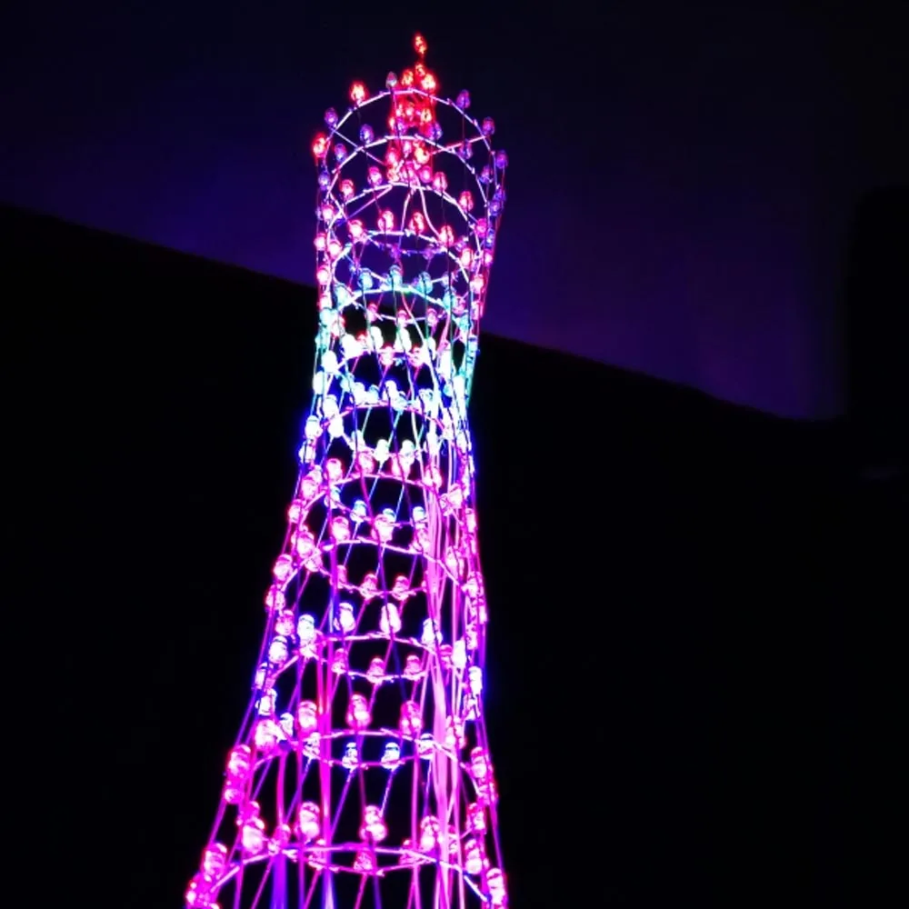
The backplane consists of a circuit board and component parts that you need to solder yourself. 278 lamps form a three-dimensional space in the shape of a small waist (about 320 LEDs are delivered) An electronic kit designed in the shape of Guangzhou Tower, a representative building in Guangzhou. With 20 kinds of offline animations, it can also transmit through bluetooth and jump with the rhythm of music, showing a very gorgeous effect. The APP version of Guangzhou Tower adopts a full plug-in design, and the welding is simple. With wireless remote control, you can switch various modes at will. (peaker is not included, need to be purchased separately)
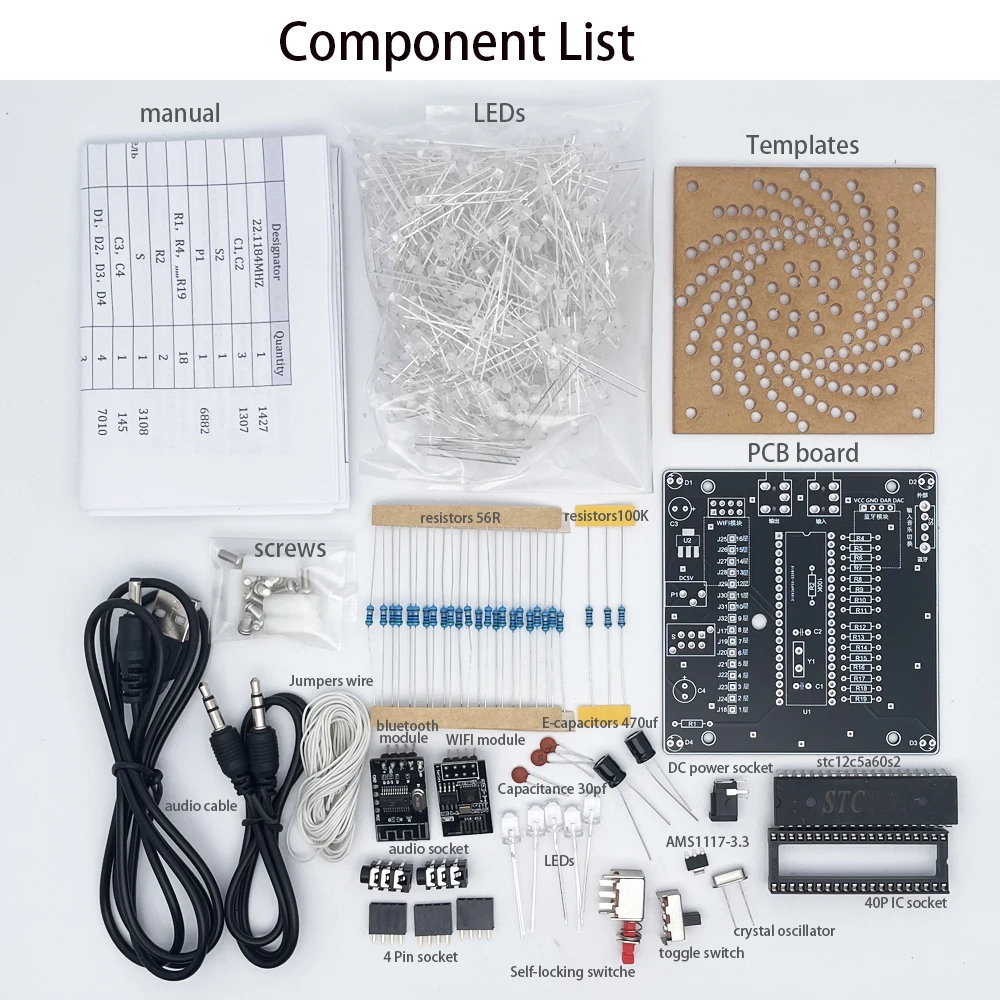
Crystals :22.1184MHZ 1pcs
Capacitance 30pf:C1, C2 2pcs
toggle switch:S2 1pcs
DC power socket:P1 1pcs
Plug-in resistors 56R:R1,R4,,,,,,R19 18pcs
Plug-in resistors100K:R2 2pcs
Self-locking switch:S 1pcs
E-capacitors 470uf:C3,C4 2pcs
LED:D1,D2,D3,D4 4pcs
4P socket 3pcs
40P IC socket:U7 1pcs
stc12c5a60s2:U7 1pcs
WIFI module:WIFI 1pcs
bluetooth module 1pcs
AMS1117-3.3 1pcs
wire 1pcs
Templates 1pcs
Brass column M3*15 4pcs
M3*6 screw 4pcs
audio socket 2pcs
audio cable 1pcs
DC3.5 power cable 1pcs
PCB board 1pcs
3mm colorful led 320pcs
The micro-controller has already downloaded the program, lease do not feel free to Download to overwrite changes
1:Motherboard soldering
the module with 8Pin is Wifi module ,
module with 4Pin is bluetooth module. Solder the main chip with the notch in the same direction as the PCB

Test after soldering the motherboard
1 soldering check
(1) short soldering this aspect needs to check themselves, please patience check
(2) Note that the direction of the chip for the chip 1 pin and the direction of the gap, solder reverse will be directly burned
Bad chip, see the arrow below!
(3) power supply check, use a multi-meter voltage file to silk screen for x, test VCC, GND
(3) power supply check, use a multi-meter voltage gear to x, test whether the short circuit between VCC, GND, whether the 5V or so. If the power supply is normal
2,Driver circuit check
(1) Simple test
Take a LED, short pin connected to any hole in the 1 layer to 16 layers, long foot received next to
a circle of any hole, power on, the LED has a light effect, that the microcontroller, the driver circuit is probably normal.
circuit is probably normal.
(2) Specific test
The LED will be made, directly into J1 to J16, without welding, directly into the
The jumper wire is soldered to the negative end of the layer and the other end is connected to the layer 1 to 16 interface in turn.
The LEDs of the layers have changed, which means that the output of J1 to J32 is normal and there is no dummy soldering or short circuit.
There is no dummy solder or short circuit.
4、LED good or bad check
(1) Repeat the simple test in (1) of the driver circuit check for each LED, this method
is to use the motherboard to test each LED to complete.
(2) Using a multimeter to test, the multimeter will be set to the on/off file or LED test file.
In short, it is a test for LEDs, the red pen is connected to the positive terminal of the LED, the black pen is connected to the negative terminal.
LED can light up that the LED is good.
5、Some layers of the tower are not lit
(1) remote control into the debugging mode, vertical debugging
(2) careful observation of the previous light does not light up the layer, in this mode in the end which light
does not light up, replace it can be.
2..Lamp assembly.
The lamp is assembled with a layer of common yin, that is, a short foot (1 layer - 16 layers) connecting one line per layer to the corresponding interface of the circuit board; the vertical common yang, that is, the long foot (J1 - J16) is connected to the interface of the board.
The vertical common sun is also known as the long foot (J1 - J16).
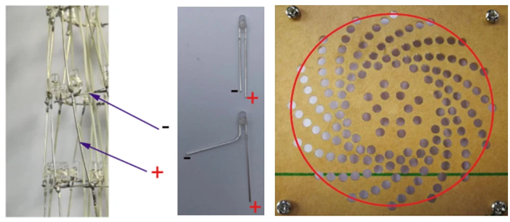
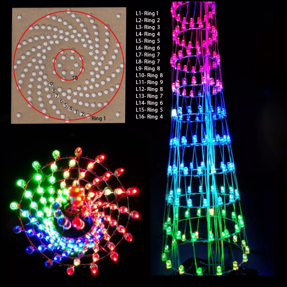
Production of the first layer of LEDs on the tower, chosen for the outer circle of stencils
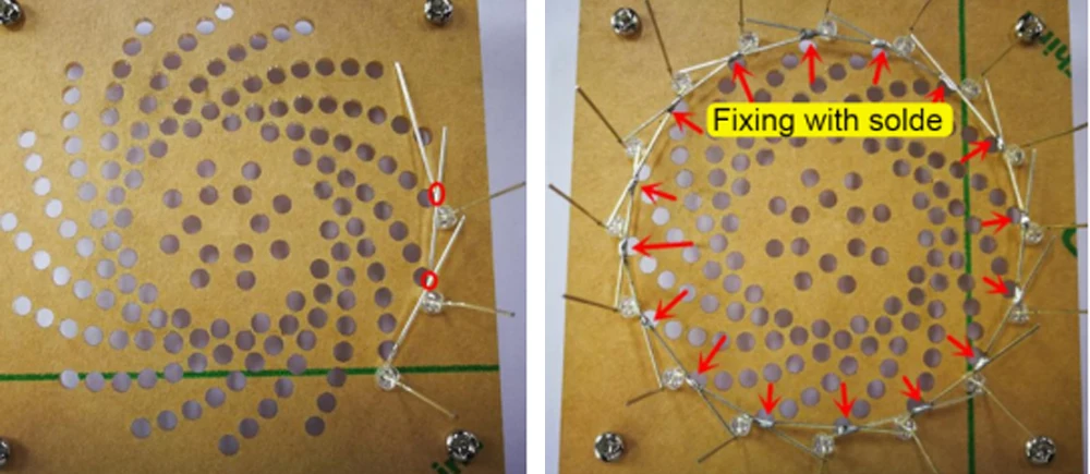
Insert the LEDs into the outermost ring of the template with the long legs facing outwards and the short legs connected together and solder them together! and so on, soldering the first ring of LEDs
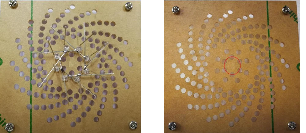
Cut off the excess pins to create the second LED layer of the tower, choosing to create it in the second circle of the template.
To make the third layer of LEDs for the tower, choose the third circle template.
To make the fourth LED layer of the tower, select the fourth circle template.
To create the fifth LED layer of the tower, choose the fifth circle template.
To create the sixth LED layer of the tower, choose the sixth circle template.
To make the seventh LED layer of the tower, select the template for the seventh circle.
To make the eighth LED layer of the tower, select the template for the seventh circle.
To make the ninth LED layer of the tower, select the template for the eighth circle.
To create the 10th layer of LEDs in the tower, choose the 8th circle stencil.
To make the eleventh layer of LEDs for the tower, choose to make them in the ninth circle of the template.
To make the twelfth LED layer of the tower, choose to make the template in the eighth circle.
To make the thirteenth layer of LEDs, choose the seventh circle of stencils.
To make the fourteenth LED layer of the tower, choose to make the template in the sixth circle.
To make the fifteenth LED layer of the tower, choose the fifth circle of the stencil.
To make the sixteenth LED layer of the tower, choose the fourth stencil circle.
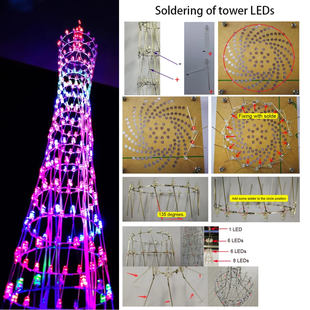
(Making the top of the tower: the distribution of lights is: 8-6-6-1-1, that is, 8 lights on the top level, 6 lights on the second level, 6 lights on the third level, 1 light on the fourth level and 1 light on the fifth level).
1 lamp on the fourth floor and 1 lamp on the fifth floor)
Step 19: Make the first layer of LEDs at the top of the tower, choose to make them in the tenth circle template, you only need 8 lights.
Step 20: Make the second and third LEDs at the top of the tower, choosing to make them in the eleventh circle template, only 6 lights are needed.
At this point, each layer of LEDs has been made and now the layers need to be connected together.
Step 1: Slightly tilt the vertical row of LED pins, the long LED legs, of each layer 135 degrees to one side.
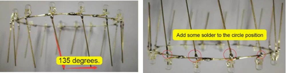 Place each layer of LEDs in a vertical column, i.e. the long LED legs, with a little solder on the bottom of the legs to to facilitate the connection between the layers
Connect the bottom of the vertical LED pins of the upper layer to the nodes of the LEDs of the lower layer.
The upper layer should also be slightly misaligned with the lower layer (generally we weld the second layer to the first layer, the third layer to the second layer, the fourth layer to the third layer and so on).
to the first layer, the third layer to the second layer, the fourth layer to the third layer, and so on).
The first level of the tower is connected to the second level, the first level of the tower is 8 lights and the second level of the tower is 6 lights
So the second level is connected to the first level with 3 lights on each side
The third level at the top and the second level are both 6 lights, so you can just connect them together
The top two tiers of the tower are both made up of one lamp, so the short leg of the top lamp is soldered directly to the third tier.
tier and the long leg to the vertical of the third tier.
Now you have to weld the top of the tower to the tower body, so that it can be connected to the 16th floor of the tower.
The feet of the first tier of the lamp are enlarged to the sides.
Use jumper wires to connect all the layers of the top of the tower to the 16th layer of the tower.
Solder the bottom layer of the tower, the vertical row of LEDs on the first layer, to the
Note that the whole tower is soldered to the side of the PCB that does not have a microcontroller.
Never solder to the side with the microcontroller
Using wire, each layer of lamps is connected to a layer 1-16 interface on the board.
The first layer is connected to the layer 1 connector, the second layer to the layer 2 connector, the third layer to the layer 3 connector, the fourth layer to the layer 4 connector, the fifth layer to the layer 5 connector and the sixth layer to the layer 6 connector.
layer 4 to layer 4, layer 5 to layer 5, layer 6 to layer 6, and so on up to layer 16.
and so on up to the 16th floor to the 16th floor. The lights at the top of the Guangzhou Tower are connected together with the negative and negative terminals.
The negative and negative terminals of the lights at the top of the tower are connected together and connected to the negative terminal of the 16th floor light with a jumper; the positive and positive terminals are connected vertically in series to the positive pin of the 16th floor light.
The positive and positive connections are strung together vertically to the positive pin of the 16-layer lamp.
(1) Solder the soldered jumper to the PCB board as shown below.
Layer 1 to layer 16 as indicated.
Then select the corresponding jumper to be soldered to the corresponding layer
Solder the wires of layer 1 to the first layer of lights, the wires of layer 2 to the second layer of lights, and so on. and so on.
3.1. Turn on the power at Canton Tower and wait a few seconds after turning it on. Turn on your mobile phone and you will see the corresponding WiFi on. No need to enter the password, just connect to the WiFi directly.
Go directly to the Guangzhou Tower App after successful WiFi connection(contact us sent app file
Once you enter the Guangzhou Tower App, you will find the main interface of the Guangzhou Tower App.
Once you enter the settings screen, only the IP address and port number can be set. But normally
Under normal circumstances, the IP address and port number do not need to be set, they have already been set, and the WiFi module in the Guangzhou
The WiFi module in the tower is also set up and turned on, but of course this is left as a
The WiFi module in the Guangzhou Tower is also set up and enabled, but of course this function is only left to accommodate future changes. The Guangzhou Tower App is also available in three languages.
The Guangzhou Tower App is also available in three languages, namely Simplified Chinese, Traditional Chinese and English.
in the animation mode, you can choose to play your favourite animations and to cycle through them all.
and loop all the animations, and you can also adjust the
speed. The speed of the animation can be adjusted in 15 steps, and the initial speed of the animation is 10.
The user can adjust the speed they prefer.
Next is the audio mode, in which there are seven spectrum modes to choose from, when playing music, you can click to select a different light audio spectrum
We then go to the edit animation screen and in the lighting control matrix we can click on a small square to control one of the corresponding lights of the Canton Tower. Here, the up, down, left and right buttons move the light you have lit up, down, left and right.
You can highlight a pattern you want to save the animation, then select it from a selection of animations to play, it rotates clockwise
Finally, there is the rotating letters, where you can enter the letters you want to rotate.
Click on play and the letters will be played on a loop.
there is the debug mode, the main function of the debug mode is to use it to check whether the DIY lights of the Canton Tower
The main purpose of this mode is to see if the DIY lights are damaged or not lit. As you can see from the instructions in the middle, the up and down buttons
The left and right buttons are for debugging - vertical and vertical lights.
Wiring diagram and how to use the music spectrum:
(1) Connect the matching power audio cable to DC5V.
(2) Connect the USB end of the power cable to the USB port of your computer or other +5V USB power supply.
1. Use Bluetooth to transfer music (when connecting Bluetooth, make sure that the Guangzhou Tower Bluetooth module is not connected to
other devices are connected) :
(1) Open your mobile phone Bluetooth - search for the device - select Bluetooth - click connect
(2) Connect the audio input cable of the audio device to the audio output connector.
(3)Play music on your mobile phone, after your mobile phone is connected to W|FI, use the Guangzhou Tower control software to tap
Tap into the spectrum display, the spectrum display is too small or large, you can adjust the player volume output
control.
Connect directly with the audio cable:
(1) Use the matching audio cable to connect one end to the audio input connector of the base board and the other end to
to a player, such as a mobile phone headphone jack.
(2) Connect the audio input cable of the audio device to the audio output interface of the base plate.
(3) Play music on your mobile phone, the remote control can call up the spectrum display by pressing 1, 4 or 8.
The spectrum display is too small or large, you can adjust the player volume output control.


500+ Sold


500+ Sold


500+ Sold


500+ Sold


500+ Sold